
Page 5 - i1052-5173-27-2
P. 5
AB
CD
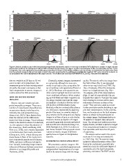
Figure 1. Seismic sections used in the interpretation experiment. (A) Seismic section in two-way travel time (TWT). (B) Seismic section in depth. (C) and
(D) stacked results of the interpreted faults in TWT and depth (respectively). The figure includes the histogram of the corresponding section. In the
histograms, the x-axis represents the possible gray values (from 0-black to 255-white) and the y-axis the number of pixels found for each value. Note
that the sections conserve the vertical scale in which they were presented to the participants and that the results in TWT were converted to depth, to
be comparable with those interpreted in the depth section. The sections are courtesy of BP/GRUPCO. Q1 and Q3—first and third quartiles.
data are available as 2D lines or 3D vol- Classically, seismic imagery is presented quality. The seismic reflection image from
umes. In spite of its importance, the as a grayscale, although it is now com- the Gulf of Suez (Fig. 1) was presented
impression given by these training materi- monly visualized in color, using either lin- either in two-way travel time (TWT, Fig.
als and by the expert community is that ear or nonlinear color spectrums (Froner et 1A)—70 subjects, 36% of the interpreta-
fault interpretation in seismic imagery is al., 2013). Nonlinear color spectrums are tions—or in depth domain (Fig. 1B)—
routine and carries little uncertainty. often used to highlight maximum and min- 126 subjects, 64% of the interpretations
imum amplitude reflectors. When employ- (Figs. 1C and 1D, respectively). The par-
HOW DO WE SEE SEISMIC ing an 8-bit black-and-white computer ren- ticipants were asked to “interpret the major
IMAGES? der, image contrast represents the range fault crossing the section and the main
in amplitude of seismic reflection data as sedimentary horizons as deep as they
Seismic data are viewed and inter- 256 pixels in different shades of gray. could.” They were also asked to provide
preted manually as images. There are a Similarly, reflection continuity (the saliency further annotation and/or sketching to sup-
number of visual factors that affect how of a reflector) is represented by adjoining port their interpretations. In this contribu-
we perceive objects, including color, pixels of the same, or a similar, shade of tion, we focus purely on the fault interpre-
intensity, hue, and perspective (e.g., gray. Modern 64-bit computers can display tations as drawn by the participants on
Froner et al., 2013). These factors deter- images in millions of gray or color shades. the seismic image. Participants had up to
mine the saliency of the different ele- However, human perception of images 30 minutes to complete their interpreta-
ments that form an image. Visual saliency presented in gray scale is poorly understood tions. The interpreters’ proficiencies were
refers to the distinctiveness of an element; and an active area of research (Song et al., highly diverse, and their experience ranged
i.e., the capacity to draw the attention of 2010; Radonjić et al., 2011). Our aim is to from unexperienced students to interpreta-
the viewer (e.g., Kadir and Brady, 2001; test if even “simple” 8-bit grayscale visual- tion specialists with more than 30 years
Kim et al., 2010), and is mainly dependent izations of seismic images of different of experience.
on its distinction from nearby elements quality have an impact on interpretation
(Cheng et al., 2011). Visual saliency pro- outcome. The seismic section used in the experi-
duces biases in favor of the most promi- ment was 31 km long and extended to
nent elements (Reynolds and Desimone, INTERPRETATION EXPERIMENT 6 s TWT (Fig. 1A). The seismic image
2003), and hence influences interpreta- included a lateral disruption of the reflec-
tion. As such, increasing image contrast We presented a seismic image to 196 tions in the central part, generally inter-
enhances differences between prominent interpreters in a controlled experiment and preted as a fault, but with some degree of
elements in an image (Reynolds and compared their interpretations of a major uncertainty as to the fault’s placement,
Desimone, 2003). fault in the seismic image with the image geometry, and extent. The TWT section
www.geosociety.org/gsatoday 5