
Page 5 - i1052-5173-27-9
P. 5
The Solution: A New World of True 3D
Terrain Models and 3D Mapping
B. Downplunge view of A. One solution to this steep-slope/cliff
problem has been around for some time
overturned syncline through the use of ground-based or air-
borne LiDAR (light detection and rang-
A. Map view of B. C. ing). High-resolution 3D renderings of
Earth’s surface can be obtained with these
pseudofolds methods, including overhanging cliff
faces. In addition, photos from any angle
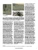
Figure 1. Examples of success and failure of 2.5D techniques for visualization of geologic features. can be draped onto the model, or the raw,
(A) and (B) show a successful visualization of an overturned syncline in the Nopah Range near Pah- colored point cloud can be visualized to
rump, Nevada, USA, where the visualization is successful due to the large size of the structure provide photorealistic scenes.
(~1 km across) relative to the terrain model. (C) shows a contrasting failure of the method in the
same area where pseudofolds are seen in this oblique view due to improper image drape on a Although LiDAR is presently the gold
narrow ridge line. Oblique view is ~500 m across. All views are from Google Earth. standard for terrain modeling, we predict
that it will never be used extensively for
2016). Digital globes eliminate one problem due to look angle. In either case, however, bedrock field geology except in special
in flat map approaches by affording an orthocorrection, and subsequent draping cases where very high accuracy is needed.
infinite range of views such as down-plunge of the orthophoto onto a terrain model, The reason is that a technology has arisen
views of folds (Fig. 1) or down-dip views produces distortions via pixel smear, dis- that makes LiDAR overpriced and ineffi-
of dipping beds that eliminates the “law- torting the image on the terrain model, or cient. That technology is SfM photo-
of-v’s” effect. Nonetheless, digital globe both. This effect is particularly signifi- grammetry. SfM has been described else-
visualizations contain errors inherent in cant when the terrain model is low resolu- where (e.g., Westoby et al., 2012; Tavani et
the way they are constructed, which is tion relative to the imagery, which is the al., 2104; Furukawa and Hernandez, 2015;
not always appreciated by geoscientists. case in virtually all visualizations that use DePaor, 2016) and is a fundamental
In particular, any recent GIS textbook a standard 30–90 m DEM (Figs. 1 and 2 advancement in photogrammetry that
describes how surface visualizations like and Data Repository supplements 1A–2B eliminates the requirement for near verti-
Google Earth are produced by a 2.5D [see footnote 1]). cal imagery in conventional photogram-
method of draping imagery, typically metry. Specifically, SfM, or more specifi-
orthocorrected aircraft imagery or satellite It is easy to show from basic trigonom- cally, multi-view stereo, allows the use of
imagery, onto a DEM. When terrain is etry that on all steep slopes (>45°) features a suite of arbitrary oblique images in the
modest, this approach produces a reason- will be either invisible or hopelessly dis- construction of a 3D terrain model (e.g.,
able rendering of Earth’s surface, but in torted in conventional map views and 3D Westoby et al., 2012; Furukawa and
steep terrain this approach produces visualizations that use a 2.5D image drape Hernandez, 2015). Most applications of
spatial errors that lead to visualization approach. Therefore, potentially critical SfM to date have been in geomorphology
problems like pixel smear and distortions information is mostly lost. Ironically, and engineering geology or in the con-
that introduce spatial errors during 3D these same cliff faces are often the most struction of virtual outcrops (e.g., Buckley
mapping (Figs. 1 and 2 and GSA Data informative rock exposures. Field geolo- et al., 2016; DePaor, 2016). We suggest
Repository supplement 11). This problem gists long have compensated for this limi- here, however, that ultimately SfM will
has been known for decades in photogram- tation by using photographs, field sketches, have its greatest application at map scales
metry (e.g., Wolf, 1983), but its effects are or both, but these observations contain commonly used in bedrock field geology,
often misunderstood. For example, con- no quantitative, 3D geographic control. particularly in areas of extensive rock out-
sider a vertical or overhanging cliff. In a Recognition of this issue was a major crop. SfM is advantageous at this scale
vertical view, the 3D surface of the cliff driver for the “Virtual Geoscience” initia- over LiDAR because (a) it only requires
is degraded to a line. Alternatively, in an tive in Europe (Buckley et al., 2016), and equipment already routinely carried by
image captured off-nadir, the cliff occupies although the problem can now be field geologists—a camera, GPS unit, and
a 2D area in the photograph, but is distorted resolved, the solution has not yet been field computer; and (b) it can be exploited
widely exploited. at sites of opportunity via construction of
virtual outcrops or at map scales, depend-
ing on project needs. Thus, there is no need
to carry an expensive extra piece of equip-
ment, and a single individual or small
group can produce a photorealistic terrain
model at resolutions of centimeters with
none of the problems of 2.5D terrain
1 GSA Data Repository Item 2017128, four supplementary figures and two animations, is online at http://www.geosociety.org/datarepository/2017/. 5
www.geosociety.org/gsatoday